
EUCHIPS Emergency LED Driver EMP40A-1B170V-RW-AS 40W 170Vdc
Product Overview
The EUCHIPS EMP40A-1B170V-RW-AS is a 40W emergency LED driver designed for back-lit panel lights, UL Listed for the US and Canada market. When the main power fails, it automatically switches to battery backup and provides up to 90 minutes of emergency output at 170Vdc. Complies with low energy consumption CEC Title 20, NFPA101 and NFPA70, with self-testing function and 5-year warranty.
Product Features
- Input voltage: 100-347Vac 50/60Hz
- Designed for back-lit panel light and UL Listed for US and Canada
- Constant output power, high output voltage
- Complies with low energy consumption CEC Title 20
- Complies with NFPA101 and NFPA70
- Self-testing function
- Flexible cable test switch and panel test switch optional
- Protection for battery: Over temperature / Over charge / Over discharge Protection
- UL924 and CSA C22.2 NO.141 certified for field installation
- 5-year warranty
Models
| Model Number | Input Voltage | Emergency Power | Output Voltage Range | Recharge Power | Recharge Time | Discharge Time |
|---|---|---|---|---|---|---|
| EMP40A-1B170V-RW-AS | 100-347Vac | 40W | 170Vdc | 12W | 24 Hours | 90 minutes |
Note: [1]. All specifications are measured at 25°C ambient temperature, input voltage 277Vac, and the typical value tested at full load. [2]. A means 0-10V dimming. [3]. The unit of EMP40A-1B170V-RW-AS for led lamp less than 320W. When the fixture dim to the minimum, the power needs to be less than that of the emergency led driver.
Technical Parameters
| Input | Rated Input AC Voltage | 100Vac | - | 347Vac | ||
| Input AC Voltage Range | 90Vac | - | 380Vac | Reference derating curve | ||
| Frequency Range | 47Hz | 50/60Hz | 63Hz | |||
| Input AC Current | - | - | 0.20A | At 100Vac input and 100% load | ||
| Input AC Power | - | - | 12W | At 100Vac input and 100% load | ||
| Leakage Current | - | - | 0.70mA | UL 8750, 277Vac/ IEC 60598-1, 240Vac, 50/60Hz | ||
| Inrush Current | - | - | 70A | At 100Vac input and 100% load, 25°C Cold Start | ||
| Stand-by Power | - | - | 1.0W | At 277Vac input | ||
| Power Factor | - | 0.5 | - | At 100~347Vac input and 100% load | ||
| Output | Output Voltage Range | 164V | 170V | 176V | ||
| Output Current Range | 224 | - | 236mA | |||
| Efficiency of Recharging | - | 70% | - | At 100% load | ||
| Efficiency of Discharge | - | 80% | - | At 100% load | ||
| Output Current Tolerance | -8% | - | +8% | At 100% load | ||
| Turn-on Delay Time | - | - | 1.0s | At 100~347Vac input and 100% load | ||
| 0-10V Dimming | Dimming Voltage Range | 0V | - | 12V | ||
| Recommended Dimming Range for 0-10V | 0V | - | 10V | Dimming prohibits reverse connection | ||
Other Characteristics
| Operating Temperature (For safety) | 0°C ~ +50°C | Humidity: 10% RH to 95% RH |
| Operating Temperature (For warranty) | 0°C ~ +50°C | |
| Storage Temperature | 0°C ~ +50°C | |
| Storage Humidity | 5%RH ~ 95%RH | |
| Short Circuit Protection | Self-recovery, short circuit without damage | |
| Lifetime (Ta=50°C) | ≥50,000 hours At 100% load | |
| Warranty | 5 years Ta 50°C | |
| Dimension | 333x59x39mm (12.33″x2.35″x1.54″) | |
Safety and EMI/EMS Standards
| Safety Certification | Standard | Status |
|---|---|---|
| UL/cUL | UL924/CSA C22.2 NO.141 (E550753) | √ |
| FCC | FCC Part15 Sub part B:2017 | √ |
| BC | CA Title 20 Appliance Efficiency Database | √ |
Dimension
333x59x39mm (12.33″x2.35″x1.54″)
Accessories (Indicator Light & Test Switch)
- 1. Test switch panel
- 2. FPC test switch
- 3. Metal integrated (Φ0.48″)
- 4. Metal integrated (Φ0.63″)
- 5. Plastic integrated (Φ0.63″)
Package
Inner Box: 412x288x260mm; Master Box: 10PCS/Carton, G.W 14kg, N.W 12kg
Wiring Diagram
Note: The LED fixture must be integrated with a 0/1-10V driver when LED fixture power is more than the emergency backup unit power.
- Figure A. Normal solution — the power of the LED fixture is equal to or greater than that of the emergency LED driver.
- Figure B. The 0-10V dimmer — the power of the LED fixture is equal to or greater than that of the emergency LED driver.
- Figure C. The DC sensor — the power of the LED fixture is equal to or greater than that of the emergency LED driver.
Related Products
-
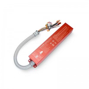
25W 170Vdc Emergency LED Driver EMP25A-1B170V-R...
-
EUCHIPS Emergency LED Driver EMP25AR-1B170V-RW-...
-
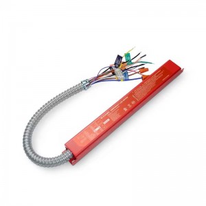
EUCHIPS Emergency LED Driver EMP18A-1B170V-RW-H...
-
EUCHIPS Emergency LED Driver EMP8A-1B170V-RW-HF...
-
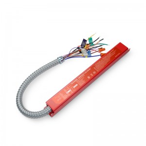
18W 100-105mA 0-10V dimming driver EMP18A-1B170...
-

EUCHIPS Emergency LED Driver EMP40AR-1B170V-RW-...